Scroll all the way to the bottom of this page for video.
QUICK INSTRUCTIONS:
Remove two mounting screws from interior of handle.
Remove old “c” clip, then retainer and spring, etc. as you see in the picture.
Install new parts in reverse order.
Note: The spring will be stiff and it may take you more than one time to get it in place.
Replace two mounting screws.
DETAILED INSTRUCTIONS:
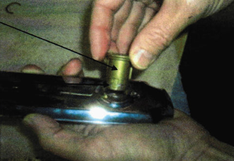
The brushing kit pictured below is brass (older style). The bushing kit you will receive is black metal. Part# 701
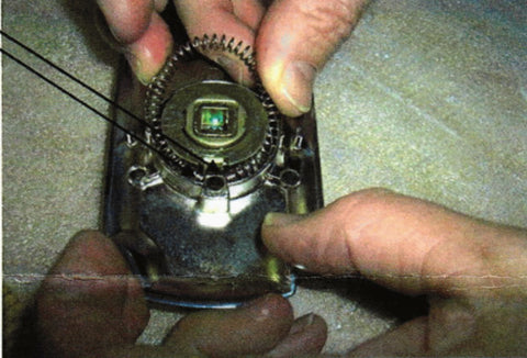
Notice the bushing is turned to the open side before it is placed in the trim plate lever bore. In the next picture you can see a stop on the lever bore that prevents the lever from over rotation. Placing the bushing, as shown, with the open area allows the bushing to rotate plus or minus about 60 degrees. Once the bushing is placed in the bore check to make sure the ClockWise (CW) and CClockWise (CCW) freedom of the bushing. Notice the groove, around the bottom of the bushing, you will use to attach the snap ring (seen in the upper left had comer of the 3rd picture down – it looks like a “C”).
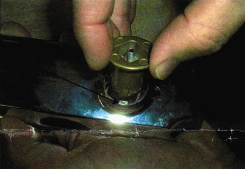
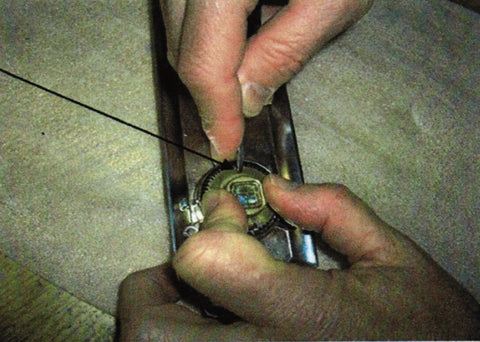
The Bushing is lowered into the lover bore Again after you have placed the bushing flush with the trim projection into the lever bore, check the CW & CCW rotation and free rotation of the bushing from stop to stop.Hold the bushing in the trim plate, turn the assembly over an place it on a soft cloth or something other non-marring surface so you can begin the assembly of the centering member spring & the snap right.The bushing must be in contact with the surface you will be working on to support the pressure applied during the assembly process that follows.
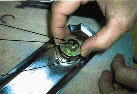
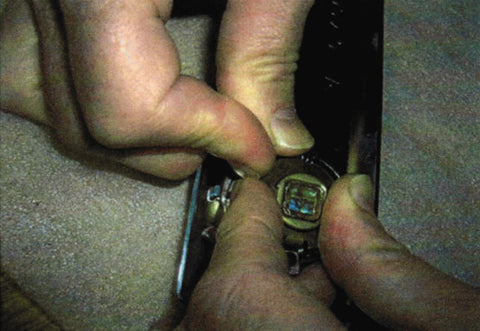
In this picture, for the first time, you see the centering member positioned properly above the lever bushing. Notice the working features of the centering member: 1. the matching inner keys on the ring for engaging the lever bushing (this ensures that they work in unison), 2. There is a tab bent down 90 degrees on the end facing the bottom of the trim – more clearly seen in the next picture. 3. This formed tab will be in contact with the one side or the other of the coil spring at all times, applying torque to the lever trying to rotate the lever to the horizontal position. 4. during the assembly the centering member will also be used to help the spring installer control the spring during the assembly of the spring to into the springs operating groove.
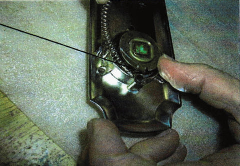
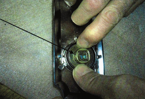
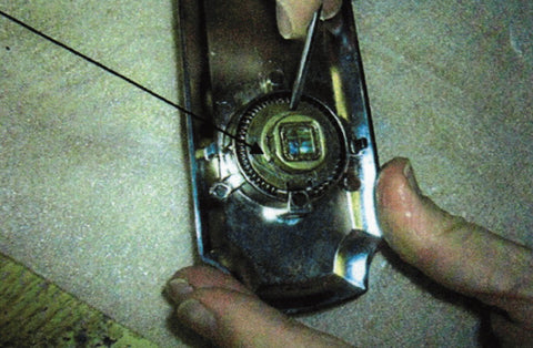
In this picture you can see who the spring is started in the groove against the centering member 90 degree tab and the fixed stop in the trim plate. Remember, to maintain control of the spring, you will need to keep down pressure on the centering member. This will create a trap for this open end of the spring. In the next picture you see the staring position of both ends of the springs positioned for compression into the spring pocket.
You can now see both sends of the spring in the start position for compression into the spring groove. Though you do not see the installers fingers controlling the centering member (CM), because we wanted you to see, the starting spring position more clearly, you WILL need to maintain the capture of the spring ends using CM down pressure with your fingers on one hand while compressing the spring into the springs toroidal groove under the CM with the other hand fingers.
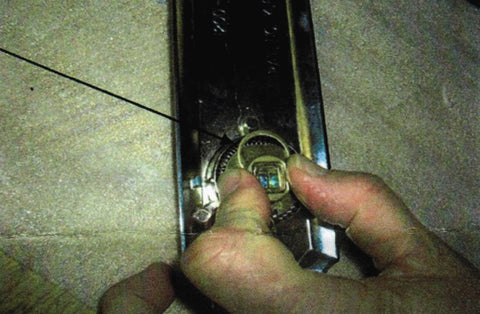
You can see this is a two hand multi finger process very difficult to photograph, as well as, do. : - ) However, it does work for the patient individual with good finger strength.Always maintain the CM down pressure, even after you have the spring in it’s circular trapped working position, until you can get the snap ring secure.
With the opposite side of the lever bushing firmly supported from behind, press the CM down until you expose the snap ring groove on the CM enough to allow you to start the snap ring end into two sides of the grove.
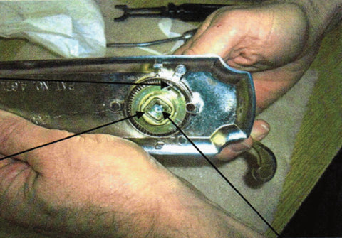
You can see the snap ring being started into the groove and finger pressure being exerted to maintain control of the CM.
We recommend you use a small instrument like the tip of a small screw drive, as shown here to press the snap ring into the groove.
The snap ring top will spring expand to accommodate the groove diameter and then should close over the diameter as the tips move past the center-line of the groove diameter. Once the snap ring nested in place you will be able to release the assembly and test the function.
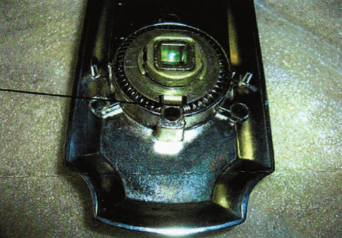
This is the lever bushing properly assembled into the trim (escutcheon) plate. Notice the closed ends of the spring in contact with the 90 degree formed down tab.
You can down check the lever function of the assembly. You can place the leer over the lever mounting screw that projects from the exterior of the lever bushing without securing it to check for rotation up or down. In this picture the lever was rotated partially to show the spring being compressed by the centering member. You should rotate the lever also in the opposite direction to ensure the range of motion necessary for full function of the assembly.